
Auxiliary Battery
- dandjcr
-
 Topic Author
- Offline
30 Oct 2012 13:45 #1
by dandjcr
David and Janet Ribbans - Oka 148
Oka148 profile here.
Visit our technical and travel blogs: here.
dandjcr created the topic: Auxiliary Battery
Forum Home > OKA Maintenance > Auxiliary Battery
Tony Lee
Member
Posts: 539
Which of the two batteries - left or right - is the auxiliary battery ie the one that gets charged last.
--
Tony
picasaweb.google.com/114611728110254134379
April 2, 2012 at 7:18 PM Flag Quote & Reply
Dandj
Member
Posts: 367
On our Oka the starter battery is on the driver's side, but the wiring can easily be changed around on the back of the dual battery switch/solenoid, so it's worth checking.
You can check by disconnecting a battery. With the dual battery switch off/key removed, if the dashboard lights and relays still turn on with the ignition switch, it's the starter battery that you disconnected since they are powered from the auxiliary battery.
--
David and Janet Ribbans, Oka 148
April 2, 2012 at 7:33 PM Flag Quote & Reply
Pete Fox
Member
Posts: 140
Tony
In my Oka LT 266, the starting battery is on the passenger side,
I always thought that the reason was that it was the closest one to the starter motor.
Pete
--
Peter Fox
OKA 266 Multi-cab.
Photobucket album
April 2, 2012 at 8:28 PM Flag Quote & Reply
Peter & Sandra James Oka 374
Member
Posts: 412
374 has the aux on the passengers side and the starting battery on the drivers side.
Peter the starter motor is on the drivers side on 374 isn't yours the same?
Also on 374 the battery switch disconnects all power to the vehicle, nothing to do with the auxilary battery at all, charging for the auxilary is via a Redarc VSR. All the auxilary battery provides power for is the winch and air compressor , it was that way when I bought it.
--
Oka 374 LT Van
April 2, 2012 at 9:01 PM Flag Quote & Reply
Tony Lee
Member
Posts: 539
Ah well, that'll teach me to be too lazy to check it out for myself. Just that it got dark a bit earlier than before - 1 hour earlier actually - and Im going to Taree very very early tomorrow and wanted to get some cable to connect from the auxiliary battery to the DC-DC charger that charges the house batteries. As a poor pensioner, I didn't want to get a couple of metres of extra cable if it wasn't necessary.
At least you have given me an easy way to check which is which.
Thanks Peter. I'd say mine might be wired up like David's since everything works normally with the red switch in the off position and only needs to be turned on to connect the two batteries together if one gets flattened. Maybe yours is a special defence force spec.
--
Tony
picasaweb.google.com/114611728110254134379
April 2, 2012 at 9:41 PM Flag Quote & Reply
Hank Onthewater
Member
Posts: 77
Sofar we have (in this thread) two starter batteries on the driver's side and one on the passenger side. I will balance things up here: mine is on the passenger's side. All the wiring looked original when I bought it, and all equipment was run from the starter battery.
The isolation switch (behind the driver's seat) just put the 2nd (aux) battery in parallel.
I changed this by adding a (Sterling) VSR and by running all additional equipment from the aux battery.
Hank
April 3, 2012 at 5:18 AM Flag Quote & Reply
Dandj
Member
Posts: 367
I think the answer is that if the Oka had only one battery originally, it was located on the LHS (passengers side). Where a dedicated starter battery (ie dual Battery system) was added it was fitted to the RHS, as these XT Manual excerpts rather confusingly suggest:
a) The battery is located on the left hand side of the vehicle at the chassis level, refer to Fig. 1.
Note: Vehicles with a dual battery system have the second optional battery located in a similar position on the right hand side.
and
b) Dedicated Starting System
Description
The dedicated starting system comprises two batteries:
1. The standard battery on the L.H.S. of the vehicle known as the auxiliary battery.
2. The dedicated starting battery located on the R.H.S. of the vehicle.
That's why all the electrics operate from the "Auxiliary" (LHS) battery and only the starter function is relocated to the Starter (RHS) battery. It makes sense for the starter battery to be closest to the the starter motor. The key switch places the aux battery in parallel with the starter battery.
However it pays to check. When I got my Oka the wiring was the other way round so I rewired it this way on the back of the solenoid/switch.
I also fitted a Sterling AR12VD alternator regulator.
--
David and Janet Ribbans, Oka 148
April 3, 2012 at 6:55 AM Flag Quote & Reply
Pete Fox
Member
Posts: 140
Whoops, the starter is on the drivers side. Blame the bottle of red for that one.
However the starting battery is on the passenger side. All current draw is from that battery including starting. The aux battery is only there as a redundant starting battery if the main battery is flat. In cooler weather I use the disconnect switch to bring it into the circuit to get the starter spinning a bit quicker. All electrics function normally with the aux battery removed.
Pete
--
Peter Fox
OKA 266 Multi-cab.
Photobucket album
April 3, 2012 at 7:49 AM Flag Quote & Reply
Rick Whitworth
Member
Posts: 74
On my previous 4WDs whenever I installed a large Auxiliary battery it was always dedicated to hungry "accessories", winch, driving lights, compressor, fridge, HF radio, live tow bar connection and other external connectors etc. The Auxiliary was charged last and flattening it had no effect on the standard battery. On one setup I also installed an overide key that would dedicate the Auxiliary back to the starter without the need to use jumper leads in the event that the Standard battery was dead .
OKAs do not work this way. #149 is wired same as XT manual as described by David with Dedicated Starting battery on drivers side and Standard battery on passenger side. Use of the name Auxilary battery in the manual to describe the Standard battery has always confused me.
I am still not sure what priority is given to the Dedicated Starting battery for recharging and how this relates to using the isolation key
Rick
April 3, 2012 at 9:17 AM Flag Quote & Reply
OKA in Africa
Member
Posts: 34
As far as I can see in the description and circuit diagram in the OKA operations manual the dual battery system charges both batteries simultaneously once the engine is starting.
There seems to be no individual regulator installed for the main and aux battery. However I realized that the batteries in my OKA are installed as the main on the RHS and aux on the LHS which is the other way around as described in the manual.
P.S.: I have now bought a Victron BMV 602S battery monitor which still needs to be installed. Anyone there who has recommendations how to run the cables for the monitor installation?
--
OKA 327 in Africa
photo album
April 3, 2012 at 9:35 AM Flag Quote & Reply
oka422
Member
Posts: 7
On the OKA standard dual battery system, both batteries are automatically connected in parallel once the alternator starts producing power. This is done by a heavy duty relay relay in parallel with the isolation switch, which is energised by the "W" output (same as the tacho signal) of the alternator. So if the alternator fails, the starter motor battery should be isolated and all electrical power drawn from the AUX battery.
The "isolation switch" manually connects the batteries should one of the batteries be flat or has been removed.
Roger
April 3, 2012 at 9:51 AM Flag Quote & Reply
Tony Lee
Member
Posts: 539
Just another bit of "useless" info.
Laid up with the main lead between the manual switch and the auxiliary battery on the passengers side is another lighter lead which feeds the fuse panel located on the left chassis rail. In this case, swapping the leads on the back of the switch would not entirely swap the battery functions around.
To avoid loading up the alternator with three batteries right from the start, my DC-DC charger has a manual switch fitted on the dash, along with a house battery volt and amp meter, so I can wait until the chassis batteries are fully charged before adding the house batteries to the load
--
Tony
picasaweb.google.com/114611728110254134379
April 3, 2012 at 8:53 PM Flag Quote & Reply
T & D Morris
Member
Posts: 29
Hi
I have set mine up with driver’s side battery as the start battery as it is closer to the starter motor.
I have a deep cycle on the left and another under the left side bed.
I control them by a marine isolation switch behind the driver’s seat.
This way if I need all the power I can get for winching I can us all the batteries.
I have gotten into the habit of starting on the starting battery each morning and 15 minutes later changing the switch to the auxiliary, if we have stopped just over night I just start on the auxiliaries.
When I had it all installed and wanted the main wiring done I went to an auto electrician who had worked up north and he wired it up so the negative when to the marine switch.
He said the up north they found that a positive wire would rub on the chassis and drain the batteries but doing this way they can’t drain.
I have had this set up for around 12 years and have never had a problem.
I just don't trust solenoids and relays.
I had my dual fuel commodore in today for service because it sometimes stalled when changing over to gas, yep faulty relay.
--
April 3, 2012 at 10:16 PM Flag Quote & Reply
Dandj
Member
Posts: 367
Oka In Africa, re:
"P.S.: I have now bought a Victron BMV 602S battery monitor which still needs to be installed. Anyone there who has recommendations how to run the cables for the monitor installation?"
You've probably seen the usage and installation guides available here and here. With your batteries on either side of the Oka it will be tricky to monitor all of your power consumption since the ground (negative) leads from both batteries would need to be connected together, and then taken to the shunt, and then to ground/chassis.
You could monitor just the auxiliary battery which is where most of the power is coming and going from, since the starter battery is only used occasionally. If you did want to monitor your total battery power (the BMV602S allows this), you would need to replace the earth strap on your aux battery with a longer thick cable across to the shunt, which would need to be near the starter battery.
The most important part will be the installation of the shunt. It needs to be installed in series with the negative (ground) lead from the battery you are monitoring (ie the aux battery if you are only monitoring that, or the starter battery if you monitor all power, with a thick ground cable across from the aux battery negative, replacing its earth strap) using the same thick starter motor cable. Keep the shunt leads short and solid as possible all the starter current passes through it. The positive supply cable can be thinner as it just monitors the voltage.
Does that help?
--
David and Janet Ribbans, Oka 148
April 4, 2012 at 6:57 AM Flag Quote & Reply
Dean & Kaye Howells
Member
Posts: 79
The standard OKA dual battery setup differs from a conventional dual battery setup in that it has a dedicated start battery and a 'does everything else' battery. In a conventional dual battery setup you have a main does everything (including start) battery and an auxiliary battery (for fridge lighting etc). So it can be a bit misleading/confusing to refer to the OKA's battery setup as main/auxiliary. It is probably better to think of the OKA's standard dual battery configuration as a start/main battery setup.
It is probably the best design possible whilst keeping true to OKA's KISS principle and not resorting to electronics.The dedicated start battery concept may be inefficient in that it makes poor use of available battery capacity but great for peace of mind knowing that there is always a fully charged battery to start the vehicle. Battery coupling using a simple solenoid with a paralled manual switch is pretty foolproof and easy to diagnose/faultfind if neccessary. Having the coupling solenoid operate from the alternator 'pulse' output is brilliant in that it only allows battery coupling when the alternator is providing an output, ie. engine running at >900 rpm (approx). This avoids oops moments when the key is inadvertantly left in the ign. or aux. position and both batterys are flat. Issues about which battery charges first are irrelevant as the start battery is always fully charged. All in all a pretty good design.
However, the good design starts to become a bit unglued when winching commences.
Winching with the engine running at <900 rpm means the batterys are not coupled so only one battery is driving the winch, not a good idea. With the engine running at >900 rpm the batterys are joined together by the battery coupling solenoid (capacity<100 amps), not nearly enough to survive typical winching currents of 400-600 amps or more with nominally half the current supplied from each battery and via the solenoid contacts. Even with the manual battery coupling switch (capacity ~125 amps) thrown the whole setup is still pretty poor.
Another potential problem is that power is always connected to the winch . A fault with the winch electrics or tampering with the winch control could result in terrible damage.
On #413 I replaced the original battery coupling switch with a larger Narva unit. The Narva switch is dual pole (as opposed to the original OKA single pole switch) and is rated at 400 amps continuous for each set of contacts. Physically its about 100mm in diameter and 50mm deep. It just fits with a little bit of metal work on the existing plate behind the drivers seat. I connected the power lead from each battery to each of the two poles of the Narva switch and commoned the other (switched) ends together with a piece of brass plate which also connects to the power cable to the winch. This overcomes the two problems described above. With the (new) battery couple switch off there is no power to the winch and the batterys are not manually coupled. With the switch on both batterys are coupled with a capacity of 400 amps continuous through each set of contacts for a max of 800 amps safely available to the winch. It is not possible to winch with the batterys uncoupled.
I have also installed an auxiliary (third) battery as a dedicated freezer battery on #413. I fed this from the main battery via a relay activated from the OKA's auxiliary power circuit. This allows the aux. battery to charge when the engine is running but not to backfeed to the main battery when stopped or when starting regardless of the position of the battery couple switch.
So essentially #413 has three batteries. A dedicated start battery, a dedicated freezer battery and a does everything else battery. The start and main batterys are identical Optima spiral wound blue top AGM batterys and the freezer battery is 3X40 = 120 Ah conventional AGM batterys. The AGM batterys cost more than conventional flooded cell batterys but are cheaper in the long term for us as they don't fail due to vibration on rough outback roads.
Deano
--
April 4, 2012 at 11:37 AM Flag Quote & Reply
OKA in Africa
Member
Posts: 34
Thanks for all the valuable and detailed input so far.
I will probably get back once I am going to install the unit.
Thanks
--
OKA 327 in Africa
photo album
April 4, 2012 at 9:32 PM Flag Quote & Reply
Hal Harvey
Site Owner
Posts: 509
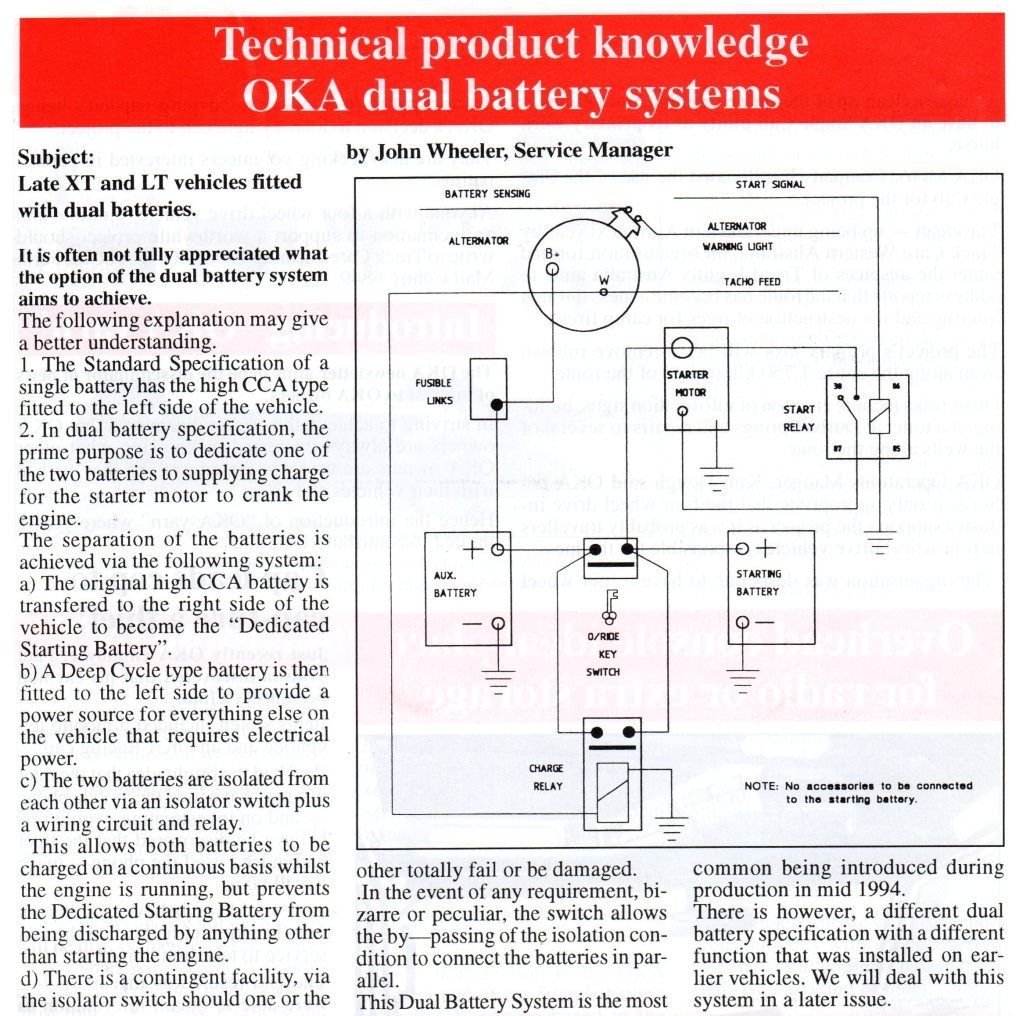
No wonder it's confusing. I found the article below in the factory's OKA News of September 1997; and it's also available as a pdf (to enlarge) in the Documents & Data pages here. It also refers to a different spec on earlier models to be discussed in a later issue... but if it ever was, I don't have the later issue.
--
Hal
August 6, 2012 at 8:05 PM Flag Quote & Reply
Outback Jack
Member
Posts: 381
I think the system I have is just a switch between both batteries.
--
August 6, 2012 at 8:58 PM Flag Quote & Reply
David Hallandal
Member
Posts: 133
RE: Auxiliary battery it was always dedicated to hungry "accessories", winch, driving lights, compressor, fridge, HF radio, live tow bar connection and other external connectors etc.
A HF Radio and Winch should always be conected to the Starting Battery. With the HF Radio you need it connected to the battery with the most grunt and after camping with a fridge running along with other power hungry accessories and find you need to make an Emergency Call then the starting battery is the isolated battery with the most power left to run the radio. Like wise a Winch will be on a Battery what is being charged from the alternator direct when you need to use it and not through a isolator
The Starting battery is on the Drivers Side. However the OKA will not start if the Auxiliary battery is flat as there is a feed to the instrument panel from this Battery
--
David Hallandal
OKA-131 Home Page
OKA Camper Trailer
XT and LT Service Manuals on CD For Sale
20mm Spring Hanger Upgrade Kits For Sale
August 7, 2012 at 8:05 AM
Tony Lee
Member
Posts: 539
Which of the two batteries - left or right - is the auxiliary battery ie the one that gets charged last.
--
Tony
picasaweb.google.com/114611728110254134379
April 2, 2012 at 7:18 PM Flag Quote & Reply
Dandj
Member
Posts: 367
On our Oka the starter battery is on the driver's side, but the wiring can easily be changed around on the back of the dual battery switch/solenoid, so it's worth checking.
You can check by disconnecting a battery. With the dual battery switch off/key removed, if the dashboard lights and relays still turn on with the ignition switch, it's the starter battery that you disconnected since they are powered from the auxiliary battery.
--
David and Janet Ribbans, Oka 148
April 2, 2012 at 7:33 PM Flag Quote & Reply
Pete Fox
Member
Posts: 140
Tony
In my Oka LT 266, the starting battery is on the passenger side,
I always thought that the reason was that it was the closest one to the starter motor.
Pete
--
Peter Fox
OKA 266 Multi-cab.
Photobucket album
April 2, 2012 at 8:28 PM Flag Quote & Reply
Peter & Sandra James Oka 374
Member
Posts: 412
374 has the aux on the passengers side and the starting battery on the drivers side.
Peter the starter motor is on the drivers side on 374 isn't yours the same?
Also on 374 the battery switch disconnects all power to the vehicle, nothing to do with the auxilary battery at all, charging for the auxilary is via a Redarc VSR. All the auxilary battery provides power for is the winch and air compressor , it was that way when I bought it.
--
Oka 374 LT Van
April 2, 2012 at 9:01 PM Flag Quote & Reply
Tony Lee
Member
Posts: 539
Ah well, that'll teach me to be too lazy to check it out for myself. Just that it got dark a bit earlier than before - 1 hour earlier actually - and Im going to Taree very very early tomorrow and wanted to get some cable to connect from the auxiliary battery to the DC-DC charger that charges the house batteries. As a poor pensioner, I didn't want to get a couple of metres of extra cable if it wasn't necessary.
At least you have given me an easy way to check which is which.
Thanks Peter. I'd say mine might be wired up like David's since everything works normally with the red switch in the off position and only needs to be turned on to connect the two batteries together if one gets flattened. Maybe yours is a special defence force spec.
--
Tony
picasaweb.google.com/114611728110254134379
April 2, 2012 at 9:41 PM Flag Quote & Reply
Hank Onthewater
Member
Posts: 77
Sofar we have (in this thread) two starter batteries on the driver's side and one on the passenger side. I will balance things up here: mine is on the passenger's side. All the wiring looked original when I bought it, and all equipment was run from the starter battery.
The isolation switch (behind the driver's seat) just put the 2nd (aux) battery in parallel.
I changed this by adding a (Sterling) VSR and by running all additional equipment from the aux battery.
Hank
April 3, 2012 at 5:18 AM Flag Quote & Reply
Dandj
Member
Posts: 367
I think the answer is that if the Oka had only one battery originally, it was located on the LHS (passengers side). Where a dedicated starter battery (ie dual Battery system) was added it was fitted to the RHS, as these XT Manual excerpts rather confusingly suggest:
a) The battery is located on the left hand side of the vehicle at the chassis level, refer to Fig. 1.
Note: Vehicles with a dual battery system have the second optional battery located in a similar position on the right hand side.
and
b) Dedicated Starting System
Description
The dedicated starting system comprises two batteries:
1. The standard battery on the L.H.S. of the vehicle known as the auxiliary battery.
2. The dedicated starting battery located on the R.H.S. of the vehicle.
That's why all the electrics operate from the "Auxiliary" (LHS) battery and only the starter function is relocated to the Starter (RHS) battery. It makes sense for the starter battery to be closest to the the starter motor. The key switch places the aux battery in parallel with the starter battery.
However it pays to check. When I got my Oka the wiring was the other way round so I rewired it this way on the back of the solenoid/switch.
I also fitted a Sterling AR12VD alternator regulator.
--
David and Janet Ribbans, Oka 148
April 3, 2012 at 6:55 AM Flag Quote & Reply
Pete Fox
Member
Posts: 140
Whoops, the starter is on the drivers side. Blame the bottle of red for that one.
However the starting battery is on the passenger side. All current draw is from that battery including starting. The aux battery is only there as a redundant starting battery if the main battery is flat. In cooler weather I use the disconnect switch to bring it into the circuit to get the starter spinning a bit quicker. All electrics function normally with the aux battery removed.
Pete
--
Peter Fox
OKA 266 Multi-cab.
Photobucket album
April 3, 2012 at 7:49 AM Flag Quote & Reply
Rick Whitworth
Member
Posts: 74
On my previous 4WDs whenever I installed a large Auxiliary battery it was always dedicated to hungry "accessories", winch, driving lights, compressor, fridge, HF radio, live tow bar connection and other external connectors etc. The Auxiliary was charged last and flattening it had no effect on the standard battery. On one setup I also installed an overide key that would dedicate the Auxiliary back to the starter without the need to use jumper leads in the event that the Standard battery was dead .
OKAs do not work this way. #149 is wired same as XT manual as described by David with Dedicated Starting battery on drivers side and Standard battery on passenger side. Use of the name Auxilary battery in the manual to describe the Standard battery has always confused me.
I am still not sure what priority is given to the Dedicated Starting battery for recharging and how this relates to using the isolation key
Rick
April 3, 2012 at 9:17 AM Flag Quote & Reply
OKA in Africa
Member
Posts: 34
As far as I can see in the description and circuit diagram in the OKA operations manual the dual battery system charges both batteries simultaneously once the engine is starting.
There seems to be no individual regulator installed for the main and aux battery. However I realized that the batteries in my OKA are installed as the main on the RHS and aux on the LHS which is the other way around as described in the manual.
P.S.: I have now bought a Victron BMV 602S battery monitor which still needs to be installed. Anyone there who has recommendations how to run the cables for the monitor installation?
--
OKA 327 in Africa
photo album
April 3, 2012 at 9:35 AM Flag Quote & Reply
oka422
Member
Posts: 7
On the OKA standard dual battery system, both batteries are automatically connected in parallel once the alternator starts producing power. This is done by a heavy duty relay relay in parallel with the isolation switch, which is energised by the "W" output (same as the tacho signal) of the alternator. So if the alternator fails, the starter motor battery should be isolated and all electrical power drawn from the AUX battery.
The "isolation switch" manually connects the batteries should one of the batteries be flat or has been removed.
Roger
April 3, 2012 at 9:51 AM Flag Quote & Reply
Tony Lee
Member
Posts: 539
Just another bit of "useless" info.
Laid up with the main lead between the manual switch and the auxiliary battery on the passengers side is another lighter lead which feeds the fuse panel located on the left chassis rail. In this case, swapping the leads on the back of the switch would not entirely swap the battery functions around.
To avoid loading up the alternator with three batteries right from the start, my DC-DC charger has a manual switch fitted on the dash, along with a house battery volt and amp meter, so I can wait until the chassis batteries are fully charged before adding the house batteries to the load
--
Tony
picasaweb.google.com/114611728110254134379
April 3, 2012 at 8:53 PM Flag Quote & Reply
T & D Morris
Member
Posts: 29
Hi
I have set mine up with driver’s side battery as the start battery as it is closer to the starter motor.
I have a deep cycle on the left and another under the left side bed.
I control them by a marine isolation switch behind the driver’s seat.
This way if I need all the power I can get for winching I can us all the batteries.
I have gotten into the habit of starting on the starting battery each morning and 15 minutes later changing the switch to the auxiliary, if we have stopped just over night I just start on the auxiliaries.
When I had it all installed and wanted the main wiring done I went to an auto electrician who had worked up north and he wired it up so the negative when to the marine switch.
He said the up north they found that a positive wire would rub on the chassis and drain the batteries but doing this way they can’t drain.
I have had this set up for around 12 years and have never had a problem.
I just don't trust solenoids and relays.
I had my dual fuel commodore in today for service because it sometimes stalled when changing over to gas, yep faulty relay.
--
April 3, 2012 at 10:16 PM Flag Quote & Reply
Dandj
Member
Posts: 367
Oka In Africa, re:
"P.S.: I have now bought a Victron BMV 602S battery monitor which still needs to be installed. Anyone there who has recommendations how to run the cables for the monitor installation?"
You've probably seen the usage and installation guides available here and here. With your batteries on either side of the Oka it will be tricky to monitor all of your power consumption since the ground (negative) leads from both batteries would need to be connected together, and then taken to the shunt, and then to ground/chassis.
You could monitor just the auxiliary battery which is where most of the power is coming and going from, since the starter battery is only used occasionally. If you did want to monitor your total battery power (the BMV602S allows this), you would need to replace the earth strap on your aux battery with a longer thick cable across to the shunt, which would need to be near the starter battery.
The most important part will be the installation of the shunt. It needs to be installed in series with the negative (ground) lead from the battery you are monitoring (ie the aux battery if you are only monitoring that, or the starter battery if you monitor all power, with a thick ground cable across from the aux battery negative, replacing its earth strap) using the same thick starter motor cable. Keep the shunt leads short and solid as possible all the starter current passes through it. The positive supply cable can be thinner as it just monitors the voltage.
Does that help?
--
David and Janet Ribbans, Oka 148
April 4, 2012 at 6:57 AM Flag Quote & Reply
Dean & Kaye Howells
Member
Posts: 79
The standard OKA dual battery setup differs from a conventional dual battery setup in that it has a dedicated start battery and a 'does everything else' battery. In a conventional dual battery setup you have a main does everything (including start) battery and an auxiliary battery (for fridge lighting etc). So it can be a bit misleading/confusing to refer to the OKA's battery setup as main/auxiliary. It is probably better to think of the OKA's standard dual battery configuration as a start/main battery setup.
It is probably the best design possible whilst keeping true to OKA's KISS principle and not resorting to electronics.The dedicated start battery concept may be inefficient in that it makes poor use of available battery capacity but great for peace of mind knowing that there is always a fully charged battery to start the vehicle. Battery coupling using a simple solenoid with a paralled manual switch is pretty foolproof and easy to diagnose/faultfind if neccessary. Having the coupling solenoid operate from the alternator 'pulse' output is brilliant in that it only allows battery coupling when the alternator is providing an output, ie. engine running at >900 rpm (approx). This avoids oops moments when the key is inadvertantly left in the ign. or aux. position and both batterys are flat. Issues about which battery charges first are irrelevant as the start battery is always fully charged. All in all a pretty good design.
However, the good design starts to become a bit unglued when winching commences.
Winching with the engine running at <900 rpm means the batterys are not coupled so only one battery is driving the winch, not a good idea. With the engine running at >900 rpm the batterys are joined together by the battery coupling solenoid (capacity<100 amps), not nearly enough to survive typical winching currents of 400-600 amps or more with nominally half the current supplied from each battery and via the solenoid contacts. Even with the manual battery coupling switch (capacity ~125 amps) thrown the whole setup is still pretty poor.
Another potential problem is that power is always connected to the winch . A fault with the winch electrics or tampering with the winch control could result in terrible damage.
On #413 I replaced the original battery coupling switch with a larger Narva unit. The Narva switch is dual pole (as opposed to the original OKA single pole switch) and is rated at 400 amps continuous for each set of contacts. Physically its about 100mm in diameter and 50mm deep. It just fits with a little bit of metal work on the existing plate behind the drivers seat. I connected the power lead from each battery to each of the two poles of the Narva switch and commoned the other (switched) ends together with a piece of brass plate which also connects to the power cable to the winch. This overcomes the two problems described above. With the (new) battery couple switch off there is no power to the winch and the batterys are not manually coupled. With the switch on both batterys are coupled with a capacity of 400 amps continuous through each set of contacts for a max of 800 amps safely available to the winch. It is not possible to winch with the batterys uncoupled.
I have also installed an auxiliary (third) battery as a dedicated freezer battery on #413. I fed this from the main battery via a relay activated from the OKA's auxiliary power circuit. This allows the aux. battery to charge when the engine is running but not to backfeed to the main battery when stopped or when starting regardless of the position of the battery couple switch.
So essentially #413 has three batteries. A dedicated start battery, a dedicated freezer battery and a does everything else battery. The start and main batterys are identical Optima spiral wound blue top AGM batterys and the freezer battery is 3X40 = 120 Ah conventional AGM batterys. The AGM batterys cost more than conventional flooded cell batterys but are cheaper in the long term for us as they don't fail due to vibration on rough outback roads.
Deano
--
April 4, 2012 at 11:37 AM Flag Quote & Reply
OKA in Africa
Member
Posts: 34
Thanks for all the valuable and detailed input so far.
I will probably get back once I am going to install the unit.
Thanks
--
OKA 327 in Africa
photo album
April 4, 2012 at 9:32 PM Flag Quote & Reply
Hal Harvey
Site Owner
Posts: 509
No wonder it's confusing. I found the article below in the factory's OKA News of September 1997; and it's also available as a pdf (to enlarge) in the Documents & Data pages here. It also refers to a different spec on earlier models to be discussed in a later issue... but if it ever was, I don't have the later issue.
--
Hal
August 6, 2012 at 8:05 PM Flag Quote & Reply
Outback Jack
Member
Posts: 381
I think the system I have is just a switch between both batteries.
--
August 6, 2012 at 8:58 PM Flag Quote & Reply
David Hallandal
Member
Posts: 133
RE: Auxiliary battery it was always dedicated to hungry "accessories", winch, driving lights, compressor, fridge, HF radio, live tow bar connection and other external connectors etc.
A HF Radio and Winch should always be conected to the Starting Battery. With the HF Radio you need it connected to the battery with the most grunt and after camping with a fridge running along with other power hungry accessories and find you need to make an Emergency Call then the starting battery is the isolated battery with the most power left to run the radio. Like wise a Winch will be on a Battery what is being charged from the alternator direct when you need to use it and not through a isolator
The Starting battery is on the Drivers Side. However the OKA will not start if the Auxiliary battery is flat as there is a feed to the instrument panel from this Battery
--
David Hallandal
OKA-131 Home Page
OKA Camper Trailer
XT and LT Service Manuals on CD For Sale
20mm Spring Hanger Upgrade Kits For Sale
August 7, 2012 at 8:05 AM
David and Janet Ribbans - Oka 148
Oka148 profile here.
Visit our technical and travel blogs: here.
Please Log in or Create an account to join the conversation.